DonShockley
T.C. Member-
Posts
493 -
Joined
-
Last visited
-
Days Won
51
Content Type
Profiles
Forums
Gallery
Everything posted by DonShockley
-
From the album: 2015 TC LWB Wagon Modifications
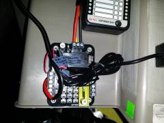
Closeup of FZ-1 FuzeBlock accessory panel with supply and accessory wiring installed. Relay provides switched power when fuses are installed between center and right connectors. Installing fuses between center and left connectors provides constant power to circuit. -
From the album: 2015 TC LWB Wagon Modifications
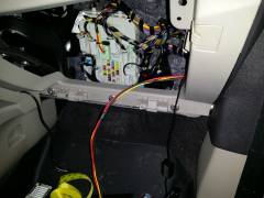
Wiring to FZ-1 FuzeBlock accessory panel exiting behind glove box. Door trim panels already reinstalled over wiring. -
From the album: 2015 TC LWB Wagon Modifications
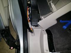
At rear corner of right rear slider door opening. Red and Yellow wires connect FZ-1 FuzeBlock accessory panel in front to cargo area fuse panel. Door trim panels already reinstalled over wiring. -
From the album: 2015 TC LWB Wagon Modifications
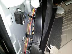
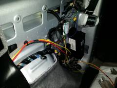
Front section under right rear cargo area trim panel. Red and Yellow wires connect FZ-1 FuzeBlock accessory panel in front to cargo area fuse panel. -
From the album: 2015 TC LWB Wagon Modifications
Rear section under right rear cargo area trim panel. Red and Yellow wires connect FZ-1 FuzeBlock accessory panel in front to cargo area fuse panel. Red spliced wire is for dealer installed trailer wiring box just above fuse box. -
towing a Transit
DonShockley replied to campergates's topic in Cargo, Hauling, Towing & Upfit Packages
The answer seems to be NO according to the second gen owners manual Pg 159: QUOTE (with bold added): Recreational Vehicle Towing Note: Put your climate control system in recirculated air mode to prevent exhaust fumes from entering the vehicle. See Climate Control (page 95). Follow these guidelines if you have a need for recreational (RV) towing. An example of recreational towing would be towing your vehicle behind a motorhome. We designed these guidelines to prevent damage to your transmission. Front-wheel drive vehicles CANNOT be flat-towed (all wheels on the ground), as transmission damage may occur. You can tow your vehicle with the front wheels off the ground by using a tow dolly. If you are using a tow dolly, follow the instructions specified by the equipment provider. -
Check your owners manual for the fuse box info. I've got a second gen and the blower is powered from a 50A Fuse (F8) on the high current battery junction box There is also a control relay (R12) in the battery fuse box There should be similar items on the first gen that you can check
-
I tried to get the dealer to add the upfitter/taxi wiring to my recent 2015 LWB wagon purchase. After initially being told it was possible by both the sales and service managers along with the shop foreman, eventually I had to talk to the "wiring specialist" for the shop who told me why it could not be done. Not only does Ford not include the wiring for the extra circuits, they don't even make it possible to use the fuse block to add the circuits. Only the supply side of the fuse has the connector. If not factory wired for an option, the load side of the fuse doesn't have anything installed. You can see there is no metal connection under the plastic cover for all the blank fuse slots. And they said even for repairs they can't order just the connectors from Ford, they have to replace the entire fuse panel. I had the dealer run some wires for me but they had splices in the middle and different colored wires on each end. I didn't like their workmanship so I redid it myself last week. To do it how I wanted cost a couple hundred dollars in parts, but that was mostly because the small pieces had a minimum order of 100. I've got enough parts on hand to repeat my install on 6 vehicles plus build connectors for another 15-20. I'll be trying to do a writeup on my modification in the next couple days. But as for the wiring diagrams, here's pix for the 2015 Transit Connect Taxi/Customer Access section. The last one is the money shot on the final hookup I did at the cargo area fuse block.
-
Roof attachment points on 2014 Transit Connect
DonShockley replied to hdrider's topic in 2014 Ford Transit Connect
I think the set offered directly from Ford are the only ones that fit. http://accessories.ford.com/exterior/racks-carriers/kit-lugg-crossbar-univ-lockable.html I ordered a set when I got my wagon with the roof rails. I am still waiting because they are on backorder. -
Since you're in the UK, shipping from CA would probably be prohibitive but here is a conversion company that sells nearly new 3rd row seats for $100. http://fordtransitconnectforum.com/topic/3155-2014-2015-third-row-seats-from-lwb-transit-connects-100shippingpair/ I was looking at the ease of adding seats when comparing Van and Wagon before making my purchase of a new 2015 Transit Connect. Retrofitting the 3rd row seats into a van is probably doable but the second row seats probably is not. The 3rd row area in both van and wagon are flat and it's likely just a matter of exposing the proper mounting points. But there are larger differences in the second row area. The van has a large plate covering the recess for the fold flat second row seats. You can see photos in this album by a forum member: http://fordtransitconnectforum.com/gallery/image/858-img-20150425-112533/ It looks like the plates are spot welded in so removal might be easy or difficult depending on your handiness and tools available. But the problem comes in mounting the new 2nd row seats. There are raised mounts that are also likely spot welded in. Trying to install the 2nd row seating would be a much more involved process than the apparent bolt in situation with the 3rd row seating. Personally, I ended up going with the wagon. The extra options included and the better interior trim was sure to help with the Texas heat. Although the raised mounts for the 2nd row seating would interfere with a flat load floor after removing them, it should should be a fairly minor problem. And fashioning a cover over the recessed footwell is sure to be a lot easier than removing spot welded in panels. I am planning to remove the seats to install the seat covers when I receive them. This will let me test the suitability of leaving them out for improved cargo capability along with how difficult it will be to install and remove them as needed for the expected rare times I have extra passengers.
-
Rear speaker harness location
DonShockley replied to LongDistanceTech's topic in Audio, Navigation and SYNC
Unfortunately, it's not any single diagram. More like half a dozen or so. A couple to show the wiring electrically, another couple to show how each individual connector is wired, and another couple to show the physical location of each connector. I spent quite a bit of time flipping back and forth through the book trying to follow all the references to other pages and parts. One update to the earlier post, that C311 connector must be under the shifter, it's not shown in another separate diagram for the console between the seats. Even though the wiring and connections spread across several pages of wire bundles and connectors, it's all just a straight run electrically from the audio system to the speakers of simple positive and negative connectors. Here's one of the diagrams showing the left side door connector location. -
Roof attachment points on 2014 Transit Connect
DonShockley replied to hdrider's topic in 2014 Ford Transit Connect
Here's some similar looking track I ran across: http://www.uscargocontrol.com/Ratchet-Straps-Tie-Downs/Airline-Straps-Hardware -
Rear speaker harness location
DonShockley replied to LongDistanceTech's topic in Audio, Navigation and SYNC
I picked up the 2015 Wiring Diagram manual from Helm last week and am still learning to use it. But it looks like the connectors are at the base of the C pillars on each side. The illustration seems to show them mounted on the front facing panel where the floor drops down for the seat recess, just inside the bottom rear corner of the door opening. Rectangular 12 pin connectors in a 3 x 4 pin pattern Connector C710 on the left, Pin 11 (WH-GN) for speaker positive and Pin 12 (BN-YE) for speaker negative Connector C810 on the right, Pin 11 (BN-WH) for speaker positive and Pin 12 (BN-BE) for speaker negative Further forward, there is a single large connector C311 centered under the instrument panel at floor level. Hard to tell exact location on the illustration, but looks near the rear most portion of the cowl under the shifter or possibly at the front of the center console base trim. A larger rectangular connector with rows of 18 pins down each side, and a more random widely spaced set of 23 wires in the middle. LR+, BN-GN audio side, pin 24, WH-GN speaker side going to C710 LR-, BN-YE both sides, pin 23 RR+, BN-WH both sides, pin 37 RR-, BN-BE both sides, pin 36 -
Here is the Ford Body Builders Layout Book which has a reference to the Upfitter Wiring Harness (86G). https://www.fleet.ford.com/truckbbas/non-html/2015/2015_Transit_Connect_v1-0.pdf But it just seems to show connections to the Taxi wiring harness. It may be the same thing just by another name. If so, you should have fuses at the rear cargo area fuse box in the following spots: F38, F41, F42, and F27. But even if those are the same circuits, it won't help with a 1500W inverter. 1500W/12v=125 Amps. The biggest of the taxi circuits is only 40A, I would think you would need some dedicated batteries for that large a demand. Although you may be able to use one of those feeds as a charging supply. I just got my 2015 Wagon last week and had been considering doing a custom order on a 2016 Van to get the Upfitter Wiring Harness. If there's no documentation and the dealer doesn't know where to access the wiring, I'm glad I didn't go that route. My whole goal would have been using OEM supplied wires for my future add-ons. Can't do that properly without documentation.
-
Ford Transit Connect Body Builders Guide
DonShockley replied to isellford's topic in Cargo, Hauling, Towing & Upfit Packages
I just got my 2015 Transit Connect Wagon last week and ordering the wiring diagram book from Helm was one of the first things I did. The book arrived yesterday. Here's photos of the interior lighting section and the customer access (aka Taxi) section. -
2014 TC, where to mount cell phone/gps?
DonShockley replied to mmontminy's topic in Accessories and Modifications
Same here. I've been moving the RAM floor mount between vehicles for 4-5 years now. I'm finalizing the deal on a new 2015 TC Wagon later today and it'll get the RAM mount too. I also started with the X-grip, but started using custom holders for easier charging. The latest being the Tylt car charger. But the first thing I do when I get any of these custom accessories is find a way to modify them to use with my RAM mounts. My favorite method is to try to find a spot I can mount a 1/4-20 nut inside with a hole drilled in the (usually) plastic case. This way it's easy to use the RAM mount when needed by screwing in a ball mount. But if I need to use the original mount I just unscrew the ball and reattach the original. -
Work out a way to reattach the hooks to the rear floor tie down points. Then you could use the motor to pull the dolly back out also. And depending on the geometry involved, it may be possible to control how the front lifts up also. Then you would have control of how the back drops to the ground. Another option would be to make the straps a continuous loop with the hooks in the middle. The you could move the dolly back and forth as needed just by reversing the drill. Here's a quick sketch I did of the picture I saw in my head as I watched the video.
- 6 replies
-
- Patent-Pending
- Hand-Crank
-
(and 8 more)
Tagged with:
