-
Posts
52 -
Joined
-
Last visited
-
Days Won
2
Content Type
Profiles
Forums
Gallery
Everything posted by Paul Hauser
-
From the album: my TC mods
-
From the album: my TC mods
-
From the album: my TC mods
-
From the album: my TC mods
-
From the album: my TC mods
-
From the album: my TC mods
-
From the album: my TC mods
-
From the album: my TC mods
-
From the album: my TC mods
finally installed the permanent accessory outlets, one on either side. I may come back later and add a USB outlet to compliment the others. -
A seatcover might cover any hole left by removing the armrest.
-

Stereo Upgrade Ford Transit Base to DDIN Carplay
Paul Hauser replied to Jon11a's topic in Audio, Navigation and SYNC
Before you buy anything be sure whether or not you have steering wheel controls. My XL (base model) only has the cruise control, not the stereo controls. -

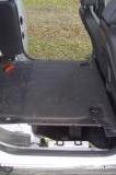
Storage Under the LWB's Load Floor Extension?
Paul Hauser replied to SteveMalone189's topic in Interior
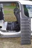
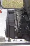
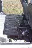
Some are welded (like the one in the photos above) but mine is bolted. I have a project in mind for mine. You'll have to peel back the carpet and look. -

My Switched Auxiliary Power Circuits
Paul Hauser replied to Paul Hauser's topic in Accessories and Modifications
The ring connectors were 5/16. Getting that nut off and back on was one of the hardest part of this project, I unsnapped the plastic housing so I could pry it back a little. I'm not looking forward to replacing that battery. :( It seemed like the best place but I don't know if I'll be able to add much more there. You could put two of those Delphi 6 way connectors back to back and use a common bar and jumper wires. I just soldered wires together to break out the power. Let us know if you have any luck removing usable parts from the salvaged fuse block. That was my initial thought but I was to cheap to get on one Ebay not knowing if Id be able to use it. -
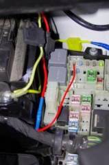
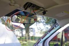
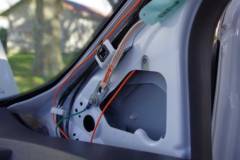
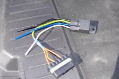
Several users have added auxiliary power circuits that are switched on with the key instead of on all the time. I was inspired particularly by DonShockley and MMontMiny, This is how I did it. This assembly was made first. The relay will power the line side of three fuses, the load side of each will be routed to the Upper console, Lower console and Rear of the van. The relay is triggered by the PAM circuit (R37 under the hood), an option not installed in my van, but it becomes hot in the Run (II) and Start (III) positions. Both the Power to the relay and the switch leg have inline fuses. I had planed to us a Tap-A-Fuse but it wouldn't fit properly. Both the wires run along the firewall to the passenger side of the van and through the grommet to below the dash behind the glovebox near the BCM. The third inline fuse seen in the photo is for trailer lights. Everything under the dash gets tucked away behind existing wiring. The coil of wire in the upper left of the photo is for future use in the lower console. Neither the Lower console or the Rear circuit will have fuses installed at this time. From under the dash two of the power circuits run up to the A pillar. One runs up the outside of the pillar and above the headliner to the hole near the rear view mirror. The other runs inside the A pillar to the top channel and to the rear of the van to be used at a later time. I used an existing fastener to ground the relay. This power socket is temporary, ultimately a socket will be mounted in the box part of the overhead console. Grounding is done at an existing threaded hole. With the shelf reinstalled this was the first objective. When I turn on the van my radar detector is powered up. A Dash cam will probably come soon, maybe front and rear. Special thanks to DonShockley for helping to source parts and wire.
-
From the album: my TC mods
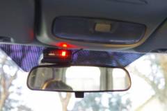
now the radar detector comes on at Run. A dash cam will probably come soon. -
From the album: my TC mods
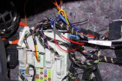
everything is tucked away behind existing wiring. -
From the album: my TC mods
An add a fuse wouldn't fit so I used a mini spade and an inline fuse to trigger the relay from the unused PAM circuit. There is also an inline fuse between the battery and the power side of the relay. The third inline fuse in the photo (Yellow one with blue tape on the splice is for trailer lights. -
From the album: my TC mods
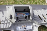
Here's where the Upper console Auxillary circuit comes out. Its grounded at an existing threaded hole. The socket in this photo is temporary, eventually they will be mounted in the box part of the console -
From the album: my TC mods
Wires powering the Upper console and Rear (wire ran for later use, no fuse installed at present) travel up the A pillar. Notice the wire to the Upper console run up the pillar and behind the headliner while the wire to the Rear (cargo area) runs inside the A pillar. An existing fastener was used for the relay ground (green wire) this only grounds the relay, not any of the other circuits so the wire can be small. -
From the album: my TC mods
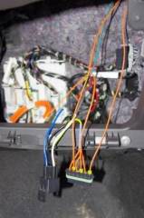
The smaller red wire is from the unused PAM circuit triggers the relay (black relay wire), the Larger red wire (blue on the relay base) is from the battery, both of these wires have inline fuses. The Three outputs (orange wires) are labeled U, L, and R for Upper console, Lower console and Rear. -

Relay, breakout, and fuse block.
Paul Hauser posted a gallery image in Ford Transit Forum Member Albums
From the album: my TC mods
This assembly has a relay that will be triggered by a switched source, I used the PAM circuit since my TC doesn't have this option. A soldered joint breaks out to three circuits each each protected by a fuse. -
I noticed on Ebay that some gen2 TCs have a center console with an armrest, like this one. My '14 TC Van has a console with an open cubby hole like this and a single armrest on the seat. Does anyone know if I could use the former type of console with the seat I have, will the armrests fit side by side? Can I remove the armrest from the seat I have? Thanks for any help or Ideas.
-

Storage Under the LWB's Load Floor Extension?
Paul Hauser replied to SteveMalone189's topic in Interior
I'm very interested in this as a few more inches in height might let me carry my scooter in the van. Neither link seemed to work right, the first said there wasn't a page at that URL the second had all the photos gone. Any further info on this? -

Any tips to remove dash and A pillar trim?
Paul Hauser replied to Paul Hauser's topic in Accessories and Modifications
What's the yellow thing near the top? It looks a little scary. Is there any danger of deploying the airbag?

