bobs
T.C. Member-
Posts
42 -
Joined
-
Last visited
Content Type
Profiles
Forums
Gallery
Everything posted by bobs
-
SYSTEM PROGRAMMING - Options (RMST) for my Gen2 bronze remote start http://ww2.justanswer.com/uploads/kennyz1963/2009-12-13_202250_rmst4.pdf I found the above link that explained how to reprogram my TC remote start. The run time for my TC remote start was just 10 min. and I wanted it to run longer. The longest dwell time that can be set is 15 min. Setting the run time to 15 min. is much better than the 10 min. it was originally set at. In addition I programmed it to remove the horn beep upon start up. Read the link as to all the changes that can be made. Note that this link was for my remote start which is the lower end of the remotes that can be installed in the TC. Mine was called the Gen 2 bronze, while others can be silver, gold etc.. The most difficult part of the reprogramming was finding the programming/override button and the LED that indicates which option was selected. I think each TC remote installation will be a little different because the remotes are dealer installed. The remote module was installed under the dash on the driver’s side. First I removed the cover for access to the fuse box, then removed a torque screw just below and to the right of this opening. The fuse box cover was seated into or onto a larger plastic panel under the steering wheel that extended from the console to the door. This panel can be removed by pulling straight out toward the driver seat, (some leverage may be required with a small pry bar, note this panel is held with clips just like the fuse box cover clips). Upon removal of this large plastic panel the sheet metal backing plate needs to be removed by removing the four metric hex bolts that hold it in place. The sheet panel removal will aid in finding the module and easier to find the programming/override button and the LED light. I had to move a few wires around to finally find the button. It was taped up with some of the module wires, and the led was taped to another set of the module wires. Note: the LED needs to be seen when setting in the driver’s seat. http://www.escape-city.com/viewtopic.php?f=3&t=5254 Go to this link to view what the button etc. look like. Yes it is for a Ford Escape but is pretty much the same as the TC setup. Follow the programming instructions, they really did work, the horn chirped and the LED worked when that option was selected. Now it just all need put back together----------GOOD LUCK PS Returned a couple months ago from a 6,000 mile trip from the east coast to the west in the TC, Mileage was great comfort was good. We stayed in many areas overnight and the bunk beds worked great. However one night in Yellowstone was pretty cold. We would have lunch at the small table while setting on the couch configuration of the beds and made really good coffee on the stove in the TC. Lot of nice comments on the little TC, How did you get all that in there?, it really looks comfortable and efficient. Headed to Florida soon Thanks all bobs
-
Auxiliary Battery Charging using Transit Truck 12 v Socket. Finally got around to do a little study of the feasibility of charging an aux. battery from 12v socket in the TC. The TC manual states that a usage load should not exceed 135 watts or about a 11 amp draw. The socket is fused with a 20 amp fuse. I don’t think I understand why there is a larger fuse employed than the recommend usage of 135 watts or about 11 amps. Oh well continue on. Had to have some kind of base line as to what the battery does while charging. So put the aux battery on an 8 amp charger just to get some kind of readings. The battery before putting on the charger was 12.4 volts, put it on the charger and voltage now measured 12.6, also used a inductive type amp meter and the reading was 7.5 amps. Now let’s take the aux battery to the truck and hook up the jumper cables. Connected cables to the battery started truck let ideal and took the reading on the aux battery 12.6 volts just like on the charger. Took amp meter reading. no or minimal reading 0+. What? I don’t think I under stand no Amp reading. Now I took a volt reading of the truck battery while idealing 13.8 v. Put amp meter around Positive battery lead ,0+ again. Wellllllllll back to the bench with question in hand. Why no amp reading? Set every thing up like the first base line check and sure enough my meter was not broken the reading from the charger Pos lead was apx 7.5 amps. Oh well continue on. Installed a female 12 v socket and affixed to the aux battery. Found male 12 v plug with 18g wire took every thing back to the TC hooked up male socket bare end wires to the jumper cables and connected jumpers to truck battery. Started the truck let ideal and pluged the male end to the aux battery female socket on the aux bttery. Took readings 12.6 v and 0+ amps. Took this set up back to the bench only now connected bare end wires of the male plug to the charger gater clips and plug male end to the aux battery and took readings, 12.6 volts and apx 7.5 amps. Now for some question. Why is there not an amp reading on the truck but there is one using the charger with the same set up? Why is the voltage on the truck set up only 12.6 and not the 13.8 volts at the truck battery. Oh well continue on. Maybe the 18g wire is to small? But using the jumper cables on the truck still had only 12.6 volts and the truck battery had 13.8 volts. So lets make a plug that goes into the TC socket with a larger wire than18g. Found some 12g stranded and put a male plug on and fused it at just 10 amps that should be safe enough if the max for the plug is about 11 amps. Took every thing back to the truck, started up and let ideal clamped bare end wires of male plug to aux battery and plugged male end into the TC socket. Took measurements 12.7 volts and still 0+ amps. Let the TC ideal for about a 30 min run and monitored volts, amps, and heat. Everything is still the same except metal tip were fuse is of the male plug when remove from TC socket was uncomfortable to hold on too. Why is it I am not getting the 13.8 volts that I am getting at the truck battery. Measured voltage at TC socket and it was 13.8volts. Oh well continue on. Took every thing back to the bench. Same result I have gotten on the bench before while on the charger. The socket on the battery should be the same 12g wire as the male plug so made new socket for the Auxiliary battery, also put another male plug on the one already made. Now I have a 2 foot section with a male plug on both ends of 12g wire and a 12” section with a female plug one end and copper battery terminals on the other end of the two wires and reconnected to auxiliary battery. Took all back to the TC and measured auxiliary battery voltage 12.4. Started TC and plugged one end of 2 foot male wire into auxiliary battery socket and plugged other end into the TC 12 v socket. Voltage reading was 12.6 and still minimal amp reading. Let the TC ideal with and occasional ideal speed at 2000 rpm after another 30 min the battery was showing sings of charging up to 12.8 volts. Conclusion; There is sufficient current to charge the aux battery and the 10 amp fuse will allow charging with out blowing and well below the 20 amp fuse in the 12v socket circuit. More to come. How does it react to a fully charge aux battery? bobs
-
I share your concerns on using the car battery, as many have pointed out a starting battery is best used for just that, starting the car. However, give it dry run try. I too thought that a fan in the back door vent would be the way to go, but have changed my mind. The reason is that if there is a slight breeze moving around you that does help in keeping you more comfortable. That is why I went with a high volume fan at low speed with the lowest amp usage I could find. My needs do require some aux. bat. as I have a medical device I need to run along with the ventilation fan. But like you how to charge it and keep it charged. In your case you could do a dry run by first deciding on the method of air movement you want, then power it up for several hours on the car battery noting the voltage drop on the bat. with a volt meter. This should give you a real life feel as to the real use factor. Also do the math of watts, amps, volts, etc. Info is all over the web how to calculate. Now back to charging the aux. bat. with capacitor dealies. One thing that researching this out is that aux. 12v sockets are not intended for long term use esp. at high amp draw. Who knows? so in the next several days I am going to simulate the truck elect setup and get some readings and especially feel the wires as to how hot they get in the simulation. No doubt the best way is to run wires from car batt. and alternator to the aux. but there has to be a safe alternative to all that cost and work for such occasional usage.
-
Thanks for the kind word. The TC is really fun to drive. Posted more pictures you may be interested in. bobs
-
Working on an idea that will provide some venting. I plan to remove the European brake light filler plate and fabricate a stainless steel hood. (think dryer vent) that will fit the opening. The vent will have to have a duct installed to the inside of the door with a gate type valve to completely close it of when needed. For this to work the cabin will have to be slightly pressurized to force interior air out side through the back door vent. To raise the pressure of the cabin I have purchased a 12v low amp draw 10" fan that will be suspended from the front overhead blowing toward the rear of the van. I have installed rain shields above each window to allow the window to be cracked without rain getting things wet. With the windows down a real concern is security. The idea I have for this yet another story. The round vents located on the pillars next to the back doors are air vents. I can not get air to flow through these vents. When the rear doors are closed the little flapper valves are held down in place and will not allow a low pressure air flow. It appears that a very high pressure is required to open them slightly. I think that the original use is to lower the pressure in the cabin when the last door is slammed shut Please follow developments in the photo gallery under Transit Conversion. Note; to see the pictures in order of posting you have to start on the last page and work backward to follow things in sequence. I can't figure out how to reverse the default order of last posting shows first. bobs
-
-
From the album: Transit Conversion
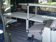
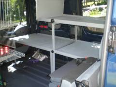
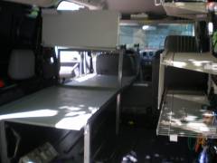
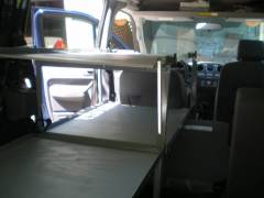
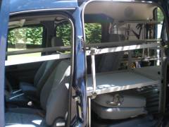
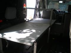
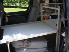
The frame work works real well for beds but also can be used as an alternative shelving. As you look toward the back you can see the offset of the upper bed. This is a two fold idea I had in that the person on the lower bunk will not feel closed in, the space is open to the ceiling. Second if rack is used for utility shelf something taller can be put into that area as well. The biggest advantage as I see it to this arrangement is that there is room for movement in and about the van, especially at night when she has to use the Porta-P. speaking of which when the rear seats are removed the prota can be placed close to the front passenger seat and where the floor drops to a lower level makes a great place to put your feet makeing the experience that much better.<br />Hope you have enjoyed these photo shots. Please stay tunned for further developments. Next up vents, air circulation, battery power off grid etc.<br /><br />Please share your comments, ideas with all and post comments in the forums Accessories and Modifications under topics Transit Conversion by bobs<br />Thanks for looking. -
From the album: Transit Conversion
The upper bunk can be shortened so as to allow the van to be driven without breaking the frame work down. The plywood platform that extended over the driver seat is relocated from the front upper section. The pin used to keep the platform over the driver seat from sliding forward is relocated back to the sissors joint to keep the two pieces of plywood from moving forward and when the rail is folded down to shorten the bed will secure ply from bouncing up. -
From the album: Transit Conversion
-
From the album: Transit Conversion
-
From the album: Transit Conversion
-
From the album: Transit Conversion
-
From the album: Transit Conversion
Head board is slid into place. Hope this keeps pillow etc. from falling down to lower bed. -
From the album: Transit Conversion
-
From the album: Transit Conversion
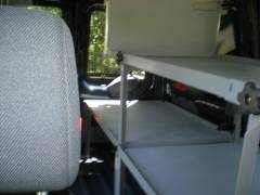
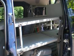
Looking in from the back doors. -
From the album: Transit Conversion
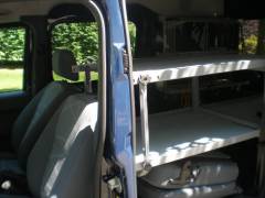
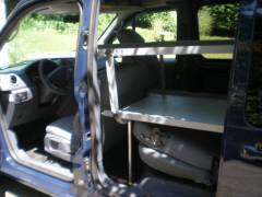
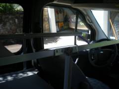
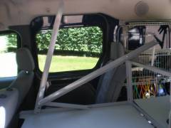
Looking to drivers side the vert support can be seen with a close up of the sissor hinge support. To keep the unit stable for laterial movement the driver side seat belt bracket is lowered onto the side channel of the upper driver side bed rail and a purple strap is inserted into slots at the end of the rails that will keep passenger side rail from opening wider that the plywood platform. -
From the album: Transit Conversion
Repeated the process for the other upper bed rail. Note that the short extension on the upper bed roll is slipped intor the lower bed frame work and secured with the black knob on that lower rail. the top knob on the upper rail is made tight to secure the two section of the upper rail and make it sturdy. -
From the album: Transit Conversion
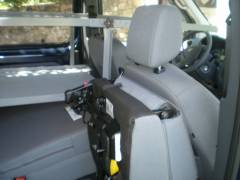
Now the fun begins. One of the upper bed side rails is put into place secured into the upper horizontal bar. The assy is then unfolded and put into place. A sissors type hinge is used to allow the rail to fully extend to 6ft. For this set up the head rest needs to be removed from the driver seat. -
From the album: Transit Conversion
Looking from the back doors at the lower bed and the rails for the upper bunk. -
From the album: Transit Conversion
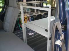
Lower bunk is assembled. This time with the two uprights in place that will make the frame work for the top bed. -
From the album: Transit Conversion
The horizontal bar is secured to the other upright . Easy to mount all joints are a slot end to make assembly faster and E Z. -
From the album: Transit Conversion
A singel bed is nice but 2 can be better. The last picture shows how a single bed can be available for use all the time. or folded up to save room, or have just a bench seat, or nothing at all except area for utility work. Now let's expand things to the second bed. Another upright is installed with a folding horizontal bar. -
From the album: Transit Conversion
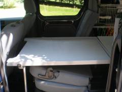
Plywood platform has been removed from the stack secured to the bench and placed in place to make a 6ft lower bed. The notch in the platform will allow extreme seat adjust should it be needed. You can see that the bed can be put in place with the seats remaining in the van, but the down side is a lot of storage under the bed can be wasted. For longer trips I think that I will remove all the back seats. Only takes a few minuetes but really increases storage space and area to move around in. -
From the album: Transit Conversion
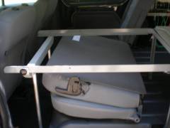
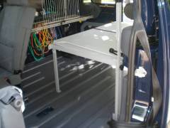
Seat is folded forward and side rails for the lower bed are slid into place and secured with the black knobs located on the bench frame work. Also a support beam has been put into place to suppor the lower bed frame. This two has removeable aluminum legs insterted into a milled 2x4. Just a note where the legs insert into the 2x4 a washer is inserted to keep the legs from etching into the wood at the bottom of the hole. Same for the feet pads. -
From the album: Transit Conversion
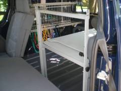
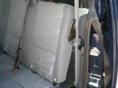
Another picture of the upright with the seat back in position. Nothing will obstruct the release of the the seat latch. Business as usual..
